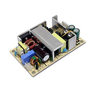
The open frame power supply is generally a switching power supply consisting of just a PCB board and no enclosure. Open frame power supplies are designed specifically to be used inside of end products with specialized designs that provide an enclosure. Typically, the whole system will share one enclosure.
Typical areas of concern when installing open frame power supplies are primarily related to safety and electromagnetic compatibility.
Safety
When mounting an open frame power supply, it is essential to evaluate the required clearance space of the equipment being used. It is recommended that at least 5mm of space be allowed for insulation between the power supply and the system chassis. Depending on the application, more insulation may be required. For instance, most general types require10mm of space, while it is typical for medical equipment to require 15mm of insulation space.
When the open frame power supply is employed, it is important to consider the ground connection for the power supply as it is a crucial part of ensuring the safety of the system and must be securely connected to the system’s safety ground. Generally this connection is made available via mounting holes or the AC input connection on the power supply.
There are usually more than one earth ground connections required which may affect the electromagnetic compatibility or EMC of the unit. This is further discussed below.
Electromagnetic Compatibility (EMC)
Open frame power supplies typically require two to three mounting points to be connected to ground. These connections are usually located on one of the mounting holes or on the AC input side of the power supply assembly, while the others are usually on the secondary side where the noise decoupling capacitors are located.
The noise decoupling capacitors (two blue capacitors shown in the pictures below) provide a low impedance path for high frequency noise to the ground. This prevents electrical noise or electromagnetic interference (EMI) from exiting the power supply and interfering with other components on the AC input. In addition, they help to stop electrical noise from appearing on the output of the power supply and interfering with the load. In some cases, just one noise decoupling capacitor is sufficient.
The above picture shows two blue noise decoupling capacitors, close to one of the mounting holes. The locations of those capacitors at the underside of the PCB (green arrow indicated) can also be seen.
The green arrow shows that the capacitors are connected to a common trace that leads to the bottom left mounting hole. This mounting hole is in fact, a plated through hole and the mounting screw and standoff will make a connection with the trace. The connection from the chassis ground to the capacitor traces must be made to meet the standards of EMC compatibility and this can be done by mounting the power supply on a grounded metal chassis, with metal standoffs and screws (as shown on the diagram below).


